Basic electricity law : EXP400030 or EXP400031
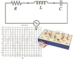
An RLC circuit is a linear circuit containing an electrical resistor, a coil (inductance) and a capacitor (capacitance). To study capacitor behaviour in DC and AC circuits, voltage is measured at the capacitor terminals, and current is determined from voltage drop in a serial-connected ohmic resistor.
An RLC circuit is a linear circuit containing an electrical resistor, a coil (inductance) and a capacitor (capacitance). To study capacitor behaviour in DC and AC circuits, voltage is measured at the capacitor terminals, and current is determined from voltage drop in a serial-connected ohmic resistor. In a circuit, potential differences at the resistor terminals as well as current strength can be calculated by applying the two Kirchoff laws: the node law and the mesh law. This experiment pack thus offers you a complete set of basic components for easy implementation of the principal basic laws of electricity.
KIRCHOFF’S LAW
At any node ( junction) in an electrical circuit, the sum of currents flowing into that node is equal to the sum of currents flowing out of that node. Current is an algebraic value (positive or negative) defined with respect to wire orientation. For example, if current in an incoming wire is 3 A, this means that this wire has an outgoing current of – 3 A.
According to the node law, we obtain : i1+i2=i3+i4. The node law is valid only if the electric field flow encircling each node remains zero or constant. It is thus not valid electrostatically.
RLC circuit
In electrokinetics, an RLC circuit is a linear circuit containing an electric resistor, a coil and a capacitor.
There are two RLC circuit types, serial and parallel, according to the interconnection of the three component types. Behaviour of an RLC circuit is normally described by a second order differential equation (where RL or RC circuits behave as first order circuits). Using a signal generator, oscillations can be injected into the circuit, and, in some cases, a resonance can be observed, characterised by a current increase.
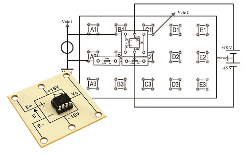
OPERATIONAL AMPLIFIER – NON INVERTING
In this study, the operational amplifier used is considered perfect and functions in “linear mode” as it uses a feedback on the AOP inverting input. Feedback on the inverting input will allow a negative feedback : all output voltage increases will reduce AOP input differential voltage. Consequently, the voltage difference between the two amplifier inputs is kept to zero. Moreover, as input impedance is infinite, no current circulates in these inputs. Voltage Ve is thus obtained at the output of the non-charged voltage divider bridge formed by R2 and R1.
SUBJECTS APPROACHED
»»Kirchhoff’s law
»»Ohms’s law
»»RLC circuit
»»DC study
»»AC study
»»Operational amplifier
NECESSARY EQUIPMENT
COMPOSITION
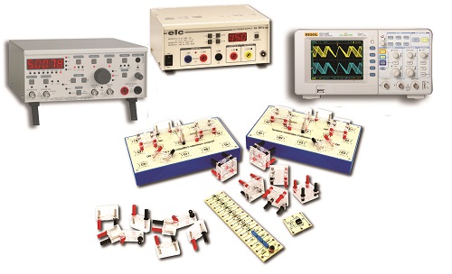
EXP 400 031 : Basic Electricity laws (BASIC)
| Reference | Description | quantity |
| PEM015600 | Universal board | 2 |
| PEM015701 | Dircet Current study | 1 |
| PEM015721 | Alternative Current study | 1 |
| PEM015630 | Component’ holder – Set of 12 | 1 |
| PEM015641 | Quadripolar jumper | 2 |
| PEM015760 | Op-amp | 1 |
COMPOSITION
EXP 400 030 : Basic Electricity laws (COMPLETE)
| Reference | Description | quantity |
| PEM015600 | Universal board | 2 |
| PEM015701 | Dircet Current study | 1 |
| PEM015721 | Alternative Current study | 1 |
| PEM015630 | Component’ holder – Set of 12 | 1 |
| PEM015641 | Quadripolar jumper | 2 |
| PEM015760 | Op-amp | 1 |
| PMM062460 | Triple adjustable power supply, 0 to ± 15 Vdc / 1A and 5 Vdc / 3 A | 1 |
| PEM080030 | Black patch cords, 100 cm – set of 10 | 1 |
| PEM080031 | Red patch cords, 100 cm – set of 10 | 1 |
| PMM062680 | Function gernerator; 5 MHz | 1 |
| EMD018015 | Digital oscilloscope, 2×100 MHz | 1 |
| PEM063700 | BNC/2x Ø 4 mm adaptator | 3 |
| PMM064620 | Decade box, resistance, 5 decades | 1 |
| PMM062901 | Multimeter, 4000 points | 2 |
- Non catégorisé
- Electrical Engineering
- PHYSICS
- Energy & Systems
- Catalogues
- PDF catalogues


