Diffraction and interferences : EXP200070 or EXP200071
This optical pack is designed to highlight the diffraction phenomenon by a number of components : slits, lines and holes.
This optical pack is designed to highlight the diffraction phenomenon by a number of components : slits, lines and holes. Influence of wavelength can also be studied in the interference and diffraction phenomena. The influence of distance, slit width and spacing in an interference system can be highlighted. Using the Caliens CCD camera, the interference or diffraction figure obtained during the exercises can be compared with the theoretical curve.
IMPLEMENTING DIFFRACTION
The diffraction phenomenon occurs when a wave encounters an obstacle whose dimensions are of the same order of
magnitude as the wavelength. The token comprising simple slits of varying widths is placed between the laser and the
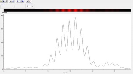
CALIENS camera (or screen) on a horizontal motion optical rider (allowing displacement along the slits of varying widths). The diffraction figure is displayed on the software. This figure consists of a central spot surrounded by dark areas and light spots. Laser wavelength and slit width can be determined by measuring the fringe spacing.
IMPLEMENTING INTERFERENCES FRINGES
The interference phenomenon occurs when two coherent waves are superimposed. When a token comprising Young’s
slits is illuminated in monochromatic light (laser), a series of dark bright fringes is observed. Using this interference
figure and, in particular, the fringe spacing value, the distance between the slits can be calculated.
IMPLEMENTING A CCD SENSOR ARRAY
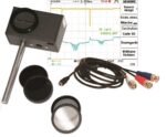
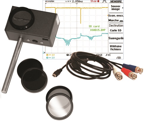
By placing the Caliens camera at the end of your optical bench, you ensure that your light signal reaches the CCD sensor array. The set of filters guarantees the signal is displayed unsaturated. The signal is displayed in real time. The software allows simulation of the signal obtained at a theoretical curve. You can simulate the type of slit and size, and the wavelength with which you work. The software displays the theoretical curve corresponding to these characteristics, which can be compared to the actual signal obtained. You can also use the BNC cable and an oscilloscope to compare the “analog raw signal” and the “digital signal” on the software.
SUBJECTS APPROACHED
»»Diffraction via a slit
»»Diffraction via a hole
»»Young’s slit interferences
»»Multiple slit interferences
»»Young’s hole interferences
»»Highlighting wavelength influence
»»The wave nature of light
»»Implementing a CCD sensor array
NECESSARY EQUIPMENT
COMPOSITION
EXP200071 Diffraction and Interferences (BASIC)
| Reference | Description | quantity |
| POF010110 | Prismatic optical bench, 2 m | 1 |
| POF010124 | Optical rider | 2 |
| POF010126 | Optical rider with horizontal motion | 1 |
| POF010300 | Basic Caliens camera | 1 |
| POD010025 | Set of filters for Caliens camera | 1 |
| POD010110 | Basic component holder | 1 |
| POD013133 | Laser diode, red | 1 |
| POD066710 | Young’s slits | 1 |
| POD066700 | Simple slits | 1 |
| POD010002 | Millimetric metal screen | 1 |
Computer is required
COMPOSITION
EXP200070 Diffraction and interferences (COMPLETE)
| Reference | Description | quantity |
| POF010110 | Prismatic optical bench, 2 m | 1 |
| POF010124 | Optical rider | 2 |
| POF010126 | Optical rider with horizontal motion | 1 |
| POF010300 | Basic Caliens camera | 1 |
| POD010025 | Set of filters for Caliens camera | 1 |
| POD010110 | Basic component holder | 1 |
| POD013136 | Laser diode, blue | 1 |
| POD013133 | Laser diode, red | 1 |
| POD013132 | Laser diode, green | 1 |
| POD066710 | Young’s slits | 1 |
| POD066700 | Simple slits | 1 |
| POD066720 | Multiple slits | 1 |
| POD066730 | Young’s holes | 1 |
| POD010002 | Millimetric metal screen | 1 |
Computer is required
- Non catégorisé
- Electrical Engineering
- PHYSICS
- Energy & Systems
- Catalogues
- PDF catalogues


